Two Tone Generator
A two tone test generator is a very useful, simple circuit that you can build to test your circuits for distortion.
 Now, switch on both the oscillators, and ajust the other oscillator until the combined peaks measure 400 mv. You adjustments are done. See the pictures. Keep the oscilloscope time base to about 1usec to get the peaks all bunched together. You can also see the two tones generating a PSK31 like waveform. The peaks are when the amplitudes add up and the nulls are where the amplitudes cancel out.
What is it
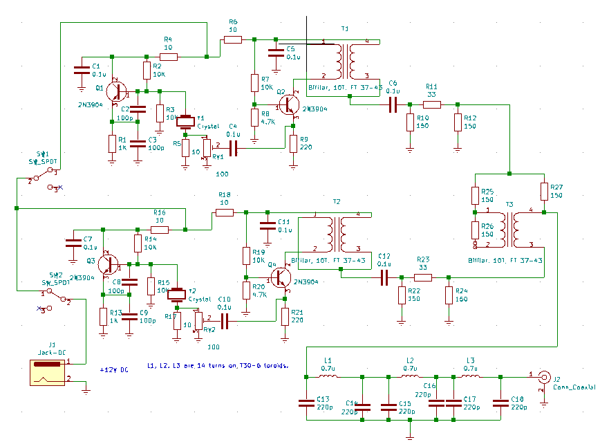
The principle is very simple, two crystal oscillators generate two signals that are close to each other. Both the oscillators are well isolated from each others output and then mixed together in a 6 db hybrid coupler. The combined output is filtered to remove the harmonics. Here is the circuit. It has just four transistors in it. You can build one in an evening.
How does it work?
Let’s imagine that the two crystals frequencies of your two tone generator (let’s call it TTG from now on) are 14 Mhz and 14.16 Mhz. They are have a difference of 160 Khz between them. If you feed the output of the TTG to an amplifier, you expect just those two frequencies to show up in the output. That only happens in an ideal world.. All real world amplifiers, mixers, even filters show distortion. The distortion will result in spurs (spurious signals) at 13.8 Mhz and 14. 4 Mhz as well. Mathematically speaking given two signals are f1 and f2, the spurs will appear at 2f1 – f2, and 2f2 – f1. These are called third-order distortions. We will deal with the math later. Enough to say for now that,- You inject the two tones, each at -10 dBm into a circut.
- Measure the output tones. An amplifier will increase the output by it’s gain. In a test case, the amplifier output was +7dbm, the gain was 7 – (-10dBm) => +17 db
- Measure the tone to distortion ratio. In this case, the distortion product was at -23dBm. Which is 30 db below the tone ( +7dbm – (-23dbm) => 30 dB)
- The Third Order Output Intercept Point(OIP3) is output power + half of distortion ratio. In this case, it was +7dBm + 30dB/2 = +22 dbm.
- The Third Order Input Intercept Point(IIP3) will be input power + half of the distortion ratio. In this case, it was -10dBm + 30dB/2 = +5 dbm
Circuit
Each of the two crystal oscillators is a conventional crystal oscillator. The unusual part is that we take the output from a small (10 ohms) resistor that is between the crystal and the ground. This is a neat trick where we use the crystal as a crystal filter as well. This where the oscillator noise is the lowest. A small value (100 ohms) preset allows you to fix the exact power output at -10 dBm at the BNC jack. The amplifier that follows is common-base amplifier, that provides very good input-output isolation. This is important as the outputs are mixed further down in the circuit and we don’t want one of the outputs leaking back into another oscillator and intermodulating it. We need almost zero inter-modulation out of this circuit so that the only intermods you can measure are from the circuit that this TTG will drive. The 6 db pads at the output of the amplifiers provides stable driving impedance to the hybrid coupler. The hybrid coupler is deceptively simple circuit. It mixes the two oscillator outputs in such a way that there is (theoretically) no reflection from one oscillator output to another. If the hybrid coupler reminds you of a return loss bridge, your guess is correct (Not now, not now). Any amplifier output has harmonics. These harmonics can interfere with the measurments. You can appreciate that if you remember that the third order intermods are caused by intermodulation of the second harmonic of one tone with another tone’s fundamental (2.f1 – f2). Hence, an extensive, 3 section Chebyschev low pass filter keeps the harmonics down. As you can see, the circuit is more elaborate than two simple crystal oscillators with their outputs tied together. Test instruments can never be over-engineered. It is a good idea to throw as much effort and care into them as possible.Construction
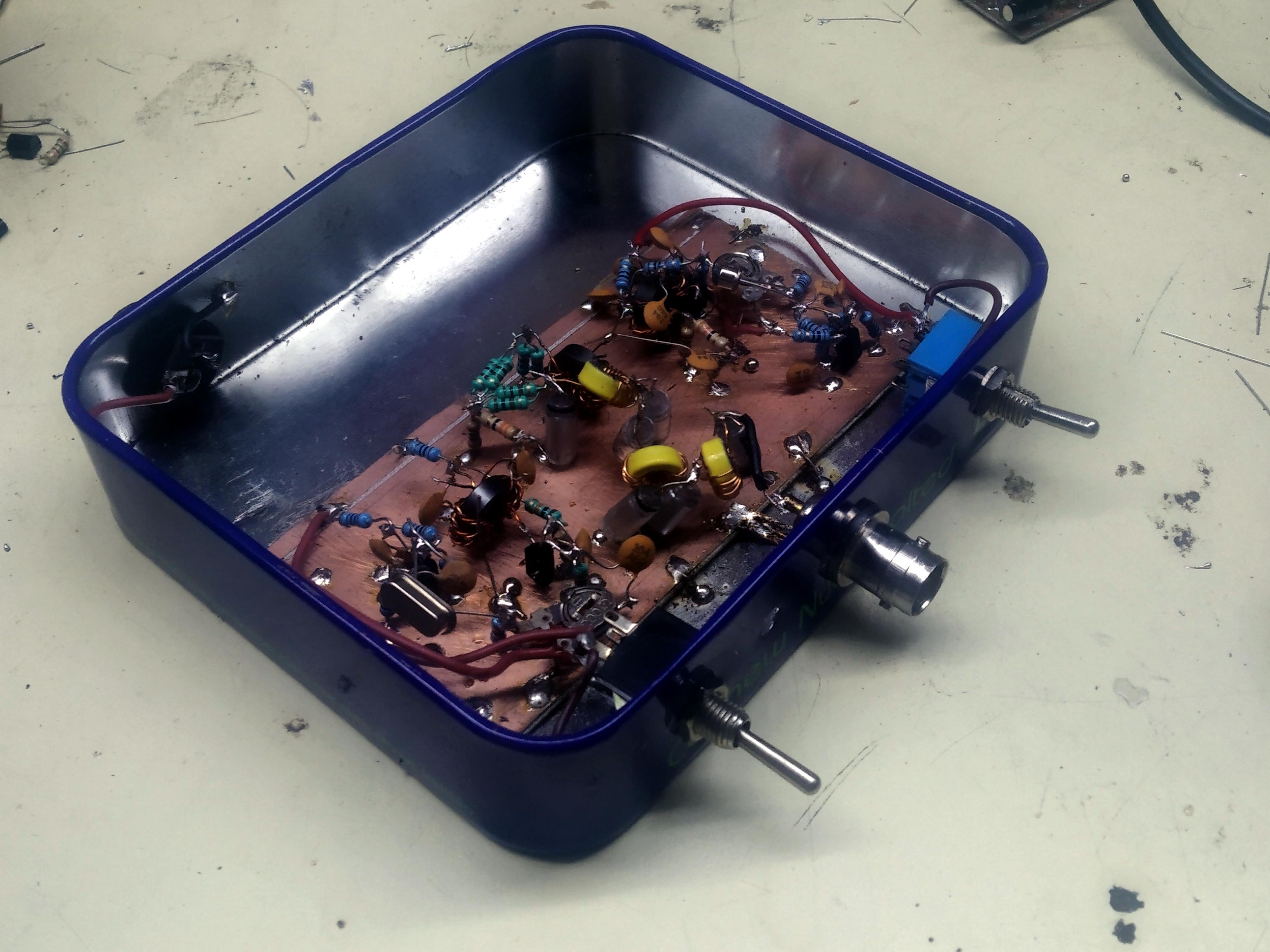
I constructed this in a small tin box that they gave on a flight with nuts in them. (No, not free, you have to buy the nuts). I built it ugly style using some stryoflex (also called polystrene) capacitors in the LPF The disc ceramics of the plain variety proved quite lossy. Depending upon the crystals you have, you may have to change the low pass filter values. The ARRL Handbook or the Experimental Methods in RF Design (Also an ARRL publication) give you the formulae to do it easily.
Calibration
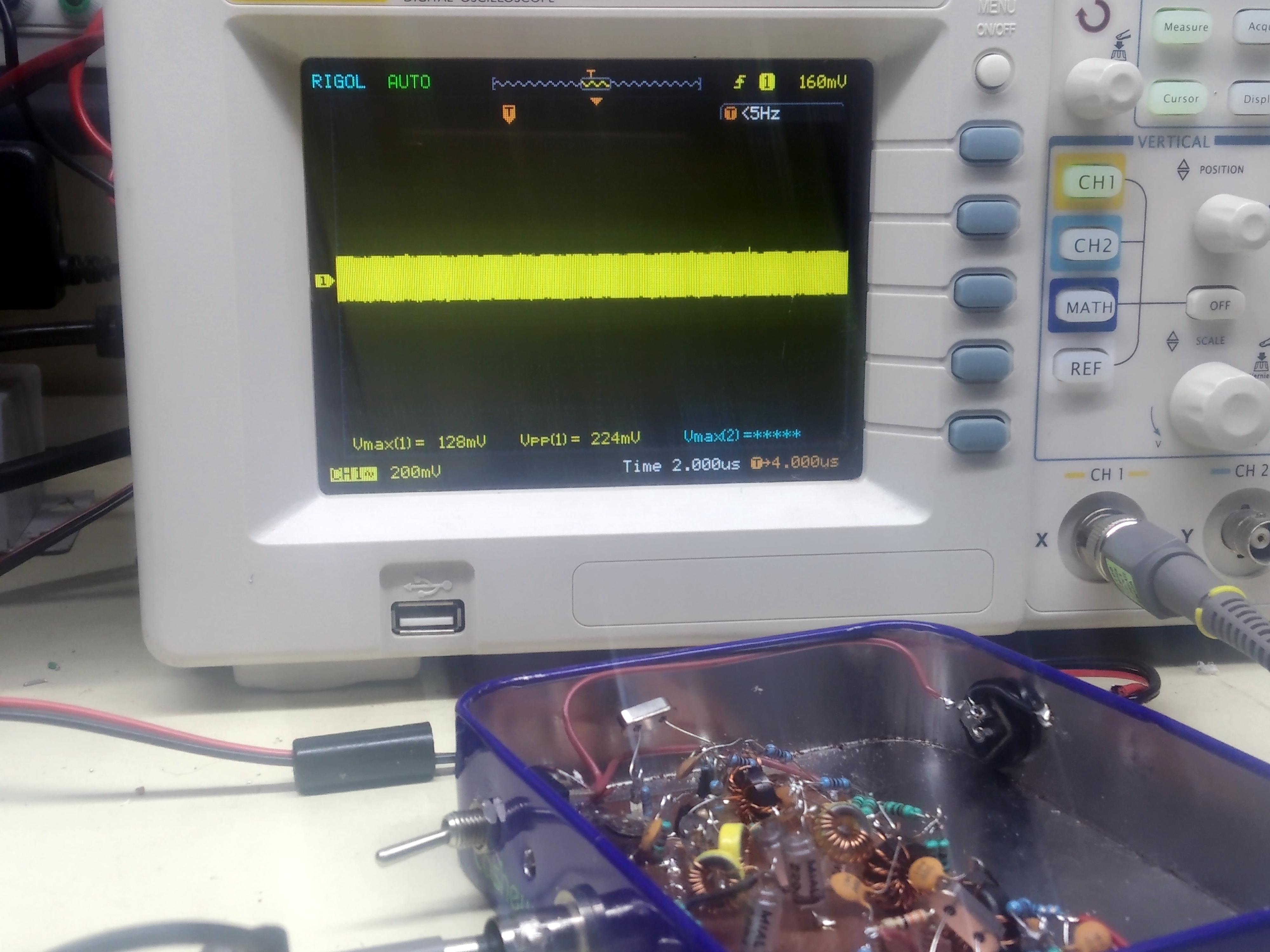
With SW1 switched off, only one oscillator will work. Connect the output to a 50 ohms load and with an oscilloscope probe, adjust the RV1 until the peak to peak RF appears to be 200 mV.
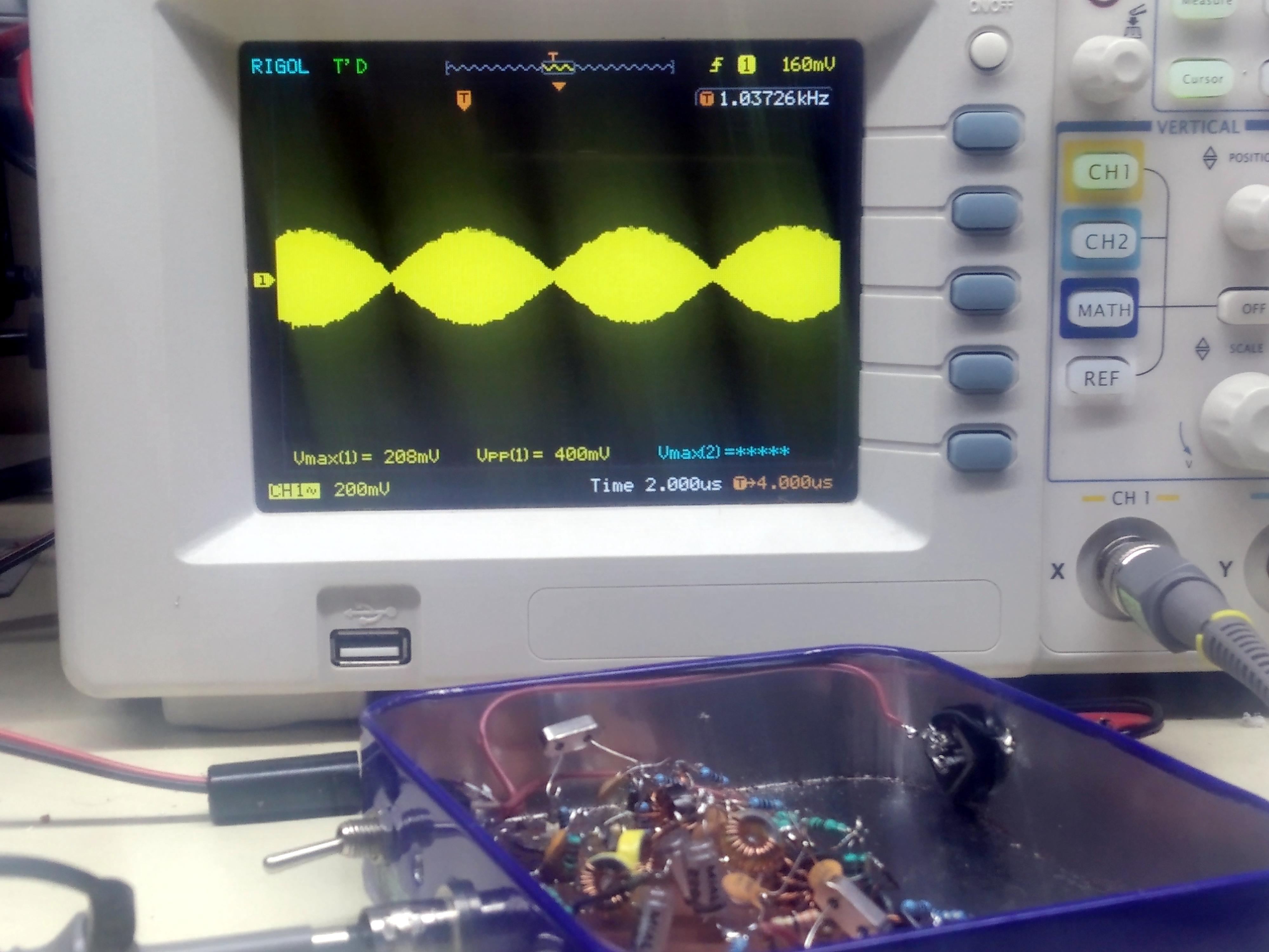
Now, switch on both the oscillators, and ajust the other oscillator until the combined peaks measure 400 mv. You adjustments are done. See the pictures. Keep the oscilloscope time base to about 1usec to get the peaks all bunched together. You can also see the two tones generating a PSK31 like waveform. The peaks are when the amplitudes add up and the nulls are where the amplitudes cancel out.
Doing it without a spectrum analyzer
The two tone generator assumes that you have a way of measuring the two tones seperately, that usually means a spectrum analyzer. But you can use your amateur radio receiver with a step attenuator. Here is how:- Turn off the AGC. It is a good thing that many homebrew receivers don’t have it to begin with!
- Connect the two tone output of the circuit to the receiver through an attenuator. Keep the attenuation to at least 40 db or you will blow the receiver!
- Tune to the spur. Note the speaker audio level with an oscilloscope.
- Now, tune to the tone. It will be very loud. Keep flip on more and more attenuation until the tone is just as loud as the spur. Measure the audio level on the oscilloscope. Now, you have the IMD ratio. You can back calculate the OIP3.
The Mathematics
Given a signal x that goes into an amplifier, the output should y such thaty = ax (The ideal case, a is the amplification factor)Instead, we get,
y = ax + bx2 + cx3 + dx4 ….This is not nice. We would ideally like b and c and d etc. to be zero so that just get ax remains. Our two tone generator helps in measuring the cx3. This is the most troublesome distortion because it produces spurs that are close to our signals. The spurs that are further away are filtered by the front-end filters or the transmitting low pass filters. Why is that so? Let’s imagine that the signal consists of two signals actually: a and b. Now, the term cx3 becomes c(a + b)3 If you remember your high school maths,
(a +b)3 = a3 + b3 + 3ab2 + 3a2bThe last two terms are multiplying the signals like : 3 . a . b . b and 3 . a . a . b We know that when signals multiply, they generate ouptut frequencies at their the sums and differences.
Multiplying signals 3 . a . b . b will generate frequencies a ± b ± c which would be: a – b – b = a – 2b (this is our offending spur) a + b – b = a (doesn’t matter, it is just a) a + b + b = a + 2b (this spur at 3 times the frequency, it will get filtered out) a – b + b = b (doesn’t matter, it is just b, again)and multiplcation of 3. a. a. b will produce the frequencies at a ± a ± b which will be:
a – a – b = -b (just b) a – a + b = +b (just b, again) a + a – b = 2a – b (this is the offending spur) a + a + b = 2a + b This is three times the frequeniecs, it will get filtered out)This is the horrible secret of the third order (beacuse it is the third term) distortion and why we struggle to overcome it. It can never be defeated but it can be controlled. Pour some more current into the amplifiers, Jake!
Leave a Reply